Compaq 6735b - Dead No Lights
This was a strange cookie.
This unit showed no sign of life and was a weird design for power in button.
I have to admit this was a 'lucky' repair. While diagnosing where was the DC power, I discovered that a power MOSFET was open, No Power anywhere, no lights, no charge and stone cold dead.
On the bottom of the board it was a mosfet FDS6676 that was open. When I replaced it with a substitute I was able to follow the DC circuit, but it dropped off at the power button. So testing that area I noticed that when I put the meter positive on point on the board the light behind the pwr button would flash briefly.
Recalling a similar experience where I had to modify another CPQ 6735 when they first came out/released. I thought I would try my luck again.
1: With the meter set to VOLTAGE and holding the meter's positive lead on this point, the unit would come on. My first guess was 47k Ohm. This worked but the laptop would not turn off, or would come on when it wanted to.
2: I would need another meter to see the resistance the meter itself presented. This turned out to be near 100k Ohm. Getting another 100k Ohm chip resistor from a dead unit, then making the leads, and adding clear heatshrink to insulate it from shorting.
3: Always test thoroughly when out of case. This way you won't have to redo, or find out something else don't work.
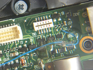
 First picture show resistor with background for clarity. The leads were added because there was no 'safe place' to tack to board. The white connector in picture is for the power button ribbon connector.
Click pictures for larger view
 This shows placement where the part will lay. Heat shrink will be slid over resistor and hot glued down.
Hot glue holds part and wires to board. Makes it easy to remove additional work is needed later. This area is covered with a L-shaped piece of black plastic insulation sheet
Final and ready to test again and then close.
Personal Note:
I always wondered why my high school Math/Algebra/Calculus teachers said 'Show Your Work'. I was one of those students that seen solutions in my head, and couldn't always say, tell why or how I got I got the answers. They were just visible in the front of my mind. Besides how can you explain something when you don't know the terms/rules and conditions of an equation, before you are taught 'the normal way'?
I quit that calculus class because I couldn't show the work, I didn't flunk I just quit it and picked another advanced science. Their loss not mine.
This unit showed no sign of life and was a weird design for power in button.
I have to admit this was a 'lucky' repair. While diagnosing where was the DC power, I discovered that a power MOSFET was open, No Power anywhere, no lights, no charge and stone cold dead.
On the bottom of the board it was a mosfet FDS6676 that was open. When I replaced it with a substitute I was able to follow the DC circuit, but it dropped off at the power button. So testing that area I noticed that when I put the meter positive on point on the board the light behind the pwr button would flash briefly.
Recalling a similar experience where I had to modify another CPQ 6735 when they first came out/released. I thought I would try my luck again.
2: I would need another meter to see the resistance the meter itself presented. This turned out to be near 100k Ohm. Getting another 100k Ohm chip resistor from a dead unit, then making the leads, and adding clear heatshrink to insulate it from shorting.
3: Always test thoroughly when out of case. This way you won't have to redo, or find out something else don't work.

Click pictures for larger view


Hot glue holds part and wires to board. Makes it easy to remove additional work is needed later. This area is covered with a L-shaped piece of black plastic insulation sheet
Final and ready to test again and then close.
Personal Note:
I always wondered why my high school Math/Algebra/Calculus teachers said 'Show Your Work'. I was one of those students that seen solutions in my head, and couldn't always say, tell why or how I got I got the answers. They were just visible in the front of my mind. Besides how can you explain something when you don't know the terms/rules and conditions of an equation, before you are taught 'the normal way'?
I quit that calculus class because I couldn't show the work, I didn't flunk I just quit it and picked another advanced science. Their loss not mine.


I'm having difficulty figuring out what to take from this piece, other than you replaced an open MOSFET and stumbled upon (I assume) an open resistor associated with the power on button. The schematic for a Compaq R4000 (http://tinypic.com/m/ayrmop/3) shows a 100K pull-up resistor connected to the power-on button but I assume the resistor you inserted went to ground, not +5V. The ONOFFBTN# in the schematic goes to the button itself, which grounds that lead when pressed, and the ON/OFF# lead goes to the ON/OFF# (pin 2) connection of a QFP176 signal processor. The data sheet for that is at http://pdf1.alldatasheet.com/datasheet-pdf/view/82583/TI/TMS320F2812PGFA.html.
ReplyDeleteAnyway, I'm a beginner at all of this and am still trying to learn what I can from your posts, which I really appreciate.
Typo: "+5V" should have read +3V.
ReplyDeleten00b question, but could you point me to a resource where I could learn more about how to test laptops with a multimeter?...I have a multimeter, and know how to turn it on, but I could use some more help. Thanks in advance.
ReplyDeleteBtw, love your website, tons of great info. You really know your stuff. :)
I can't speak for Evan, but there is a good introduction to electronics and use of test gear at http://www.allaboutcircuits.com/vol_6/index.html. Not specific to computers, but much of the information should still be helpful.
ReplyDeleteGood link Larry
ReplyDeleteI tend to forget that I had to start once too. Though the site was intended for certified or skilled techs. Sometimes it may bring out the 'wonder' in younger people to motivate toward a challenging career.
Remember a tech is a tech until they make their own path. Then they become a engineer, designer, or move on to something that's easier.
generally the cpq6735s have 5blink error code and the problem is with the ati radeon northbridge.replacing that chips restores the problem we have fixed 7 laptops with same problem.
ReplyDeleteregards
Guruji
I can't understand, i see where it stars but I can't see where does it finish, where did you put it in the end cuould you tell me for 100k where did you put it on
ReplyDeletei have cpq6735b, I see 100k is put on pin 2 but i can't see where did you put it on the end. could you tell me details please,
ReplyDeletesincerely, Btoska
Btoska- the other side goes to Ground. there was no Ground in that area, so I had to go to the other side of the board.
ReplyDelete